
RGB LED - Circuit Set-up#
Follow the schematic seen below to set-up your circuit
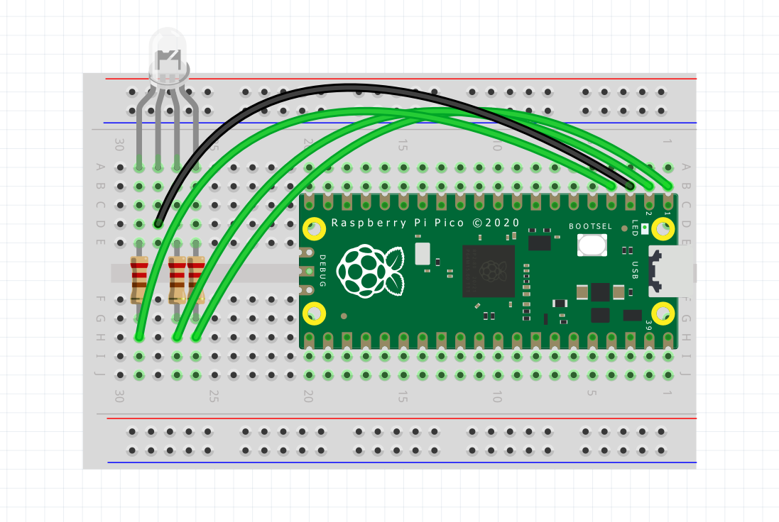
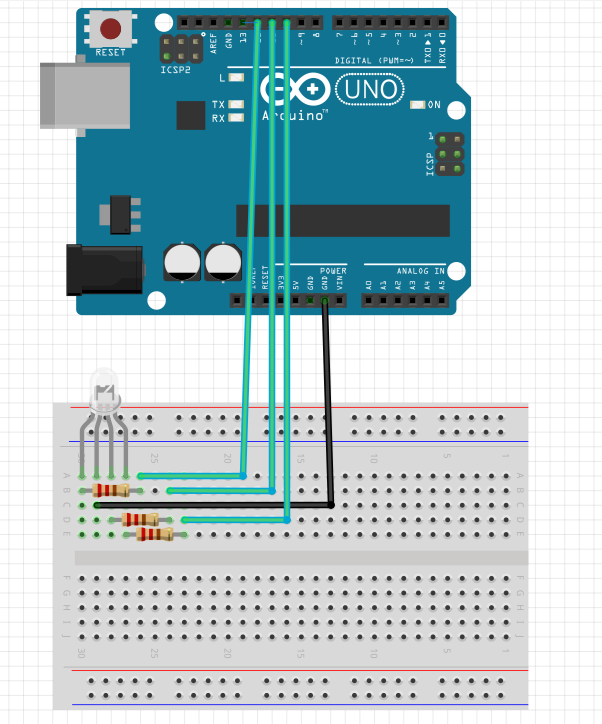
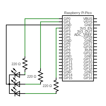
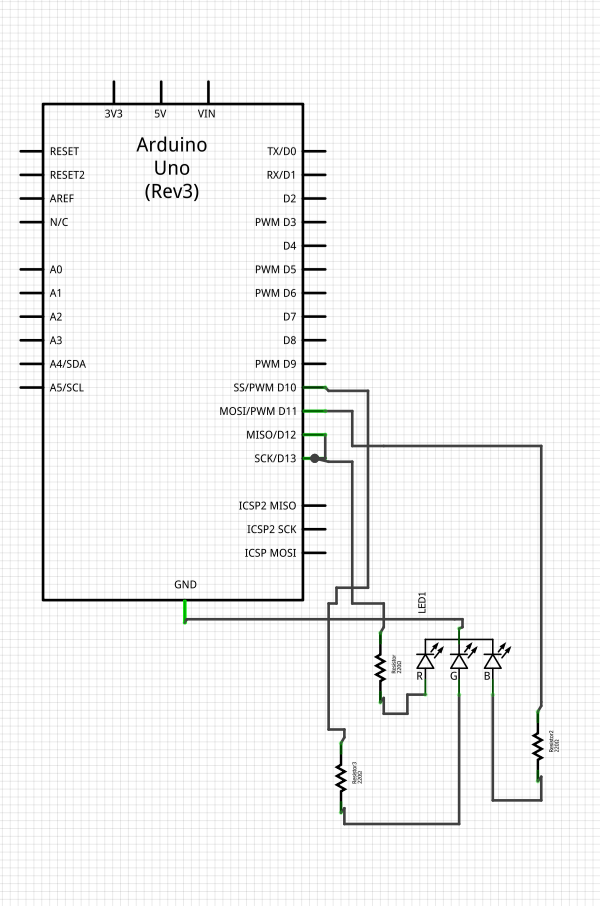
Bare in mind that like regular LEDs, the arrangement of the pins is important:

The red, green and blue pins control the red, green and blue light sources within the bulb respectively.
Pulse Width Modulation (PWM)#
So far, we have only seen digital outputs that can be set to either High/True or Low/False.
Pulse Width Modulation is a trick to allow a range of outputs inbetween High and Low by very quickly varying digital signals.
PWM works by changing the duty cycle of a digital signal. The duty cycle is the ratio of time the signal is on versus off and is typically measured as a percentage.
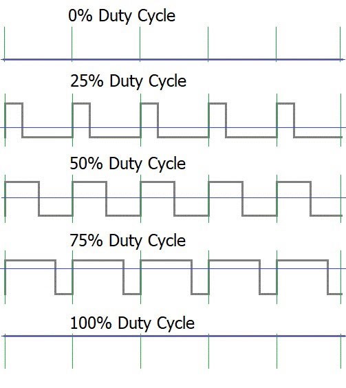
A duty cycle of 0% means the signal is constantly Low. This is identical to a Low digital output - at around 0V.
A duty cycle of 100% means the signal is constantly High. This is identical to a High digital output - at around 3.3V.
At intermediate duty cycles, the signal rapidly switches between high and low at the given ratio. This yields an effective average voltage which is a % of the High output - e.g. 40% duty cycle ~ 1.3V.
Pulse width modulation is very useful for a number of digital outputs as it allows them to emulate analog signals and vary their intensity. Here it is used to vary the brightness of LEDs.
Note
All GP pins on the Pico can perform Pulse Width Modulation.