
Automated LED - Circuit Set-up#
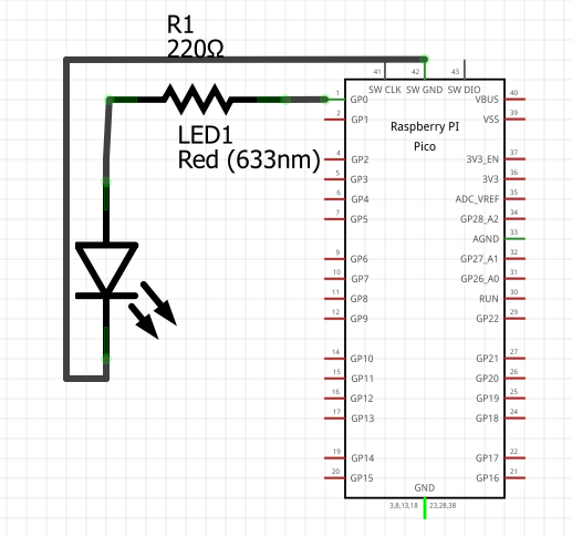
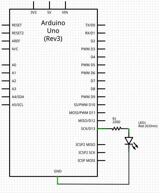
Provided below are diagrams showing how you should connecting your LED, resistor and microprocessors. You can follow whichever diagram you find more helpful - they both show the same thing just in different styles.
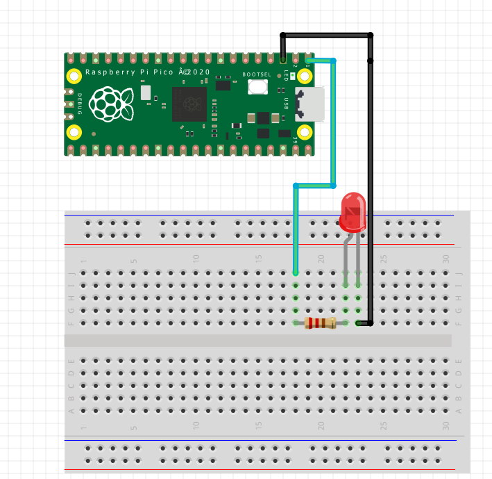
Note: The LED’s bent pin in the diagram represents the positive (longer) pin
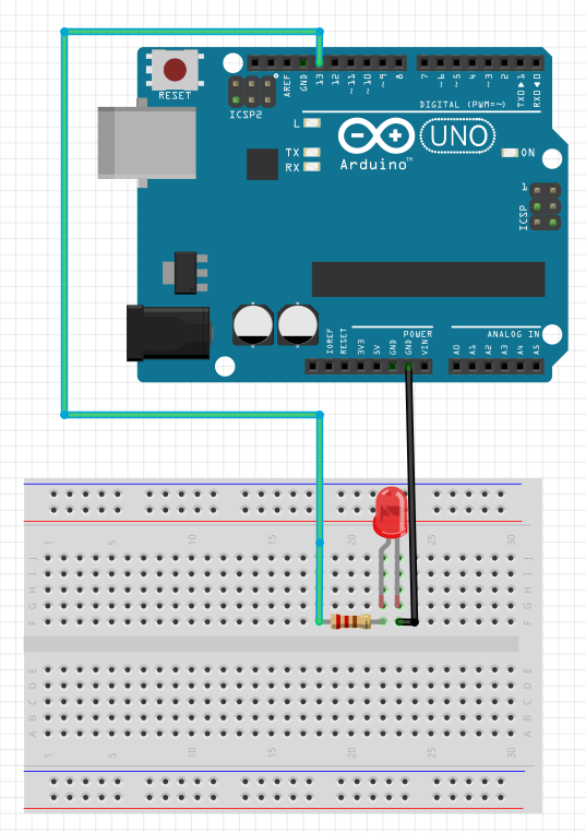
Note: The LED’s bent pin in the diagram represents the positive (longer) pin
Note
On breadboards, pins along each row (shown highlighted in green above) are electrically connected. This means it does not matter which hole along the row you chose.
Pins in the same column or on opposite halfs of the middle gap are not connected. For more description see here.
In this circuit, power is supplied from our chosen pin on the microprocessor to the LED via the green wire. Since our output here is a simple digital signal, we can choose to make a connection with any of the 28 GP pins available from the Pico board. Here, we are using GP0.
In turn, the black wire connects the LED to the ground pin, which acts as a zero point reference for the voltage and ensures the flow of current.
Wiring
Wires are usually given different colours depending on their purpose:
Green = Connections between digital pins and circuit components
Blue = Connections between analog pins and circuit components
Black = Connections between circuit components and a Ground (GND) pin
Red = Connections between power-in source and input components
White = Any other connections
It is important to notice notice that LEDs are polarised - meaning they will only function if they are in the correct orientation. For all LEDs, the longer pin is positive and must be connected to the power supply while the shorter pin is negative and must go to ground.
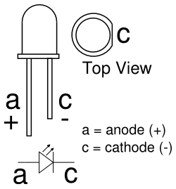
Not all circuit components are polarised, but in many cases it is important to keep orientation in mind when building your circuits.
Important
For certain components like LEDs, resistors should be placed between the power source and the component to limit the current passing through.