LED with a Button - Circuit Set-up#
Seen below is the schematic you should follow for setting up your circuit
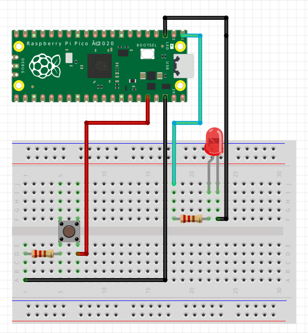
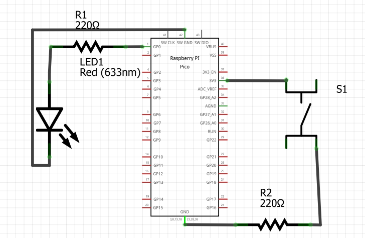
Note: The LED’s bent pin in the diagram represents the positive (longer) pin
While the diagram may look more complex, you can think of it as two separate circuits:
The first circuit connects the button to the Pico - allowing the Pico to measure when the button is being pushed or not.
The second circuit connects the LED to the Pico as seen before.
It is tempting, but wrong, to imagine that the button is directly switching on and off the LED’s power. Instead, the Pico separately measures the state of the button as on or off and then supplies voltage to the LED accordingly.
Wiring inputs#
Compared to outputs, input components typically an extra ‘power-in’ (or Vcc) connection to the Pico.
To understand how this set up leads to well-defined digital input, consider the circuits when the button is pressed versus not.
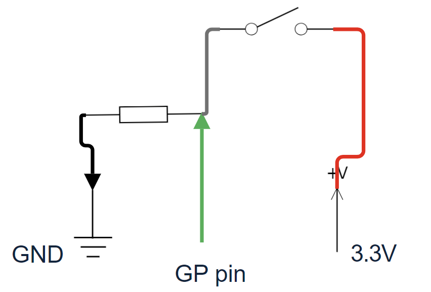
The switch being opened prevents the 3.3V pin from being connected to the input pin via the red wire.
The input pin is instead connected to the Ground pin via the resistor.
This means that the input pin measures a low voltage - effectively zero.
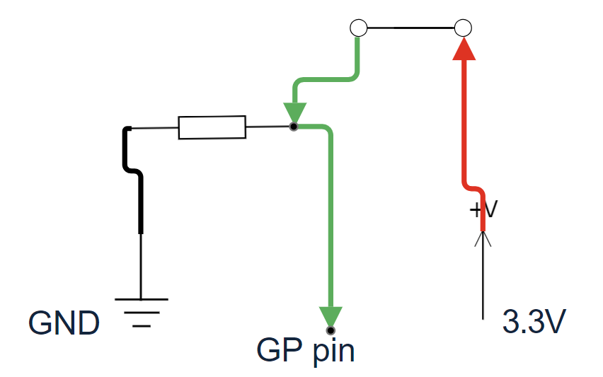
The switch is now closed and the 3.3V pin can supply voltage into the circuit.
The input pin is now receiving voltage from the 3.3V pin
The input pin now measures a high voltage (or
True).
Note
The resistor that connects the input pin to the Ground pin is known as a pull-down resistor. Without it, the input pin can be affected by random electrical noise and not correctly reads a stable low voltage. For more details check this article
Other inputs
A button is perhaps the most basic input we can have. However, it is very common for sensors and other inputs to work in a similar way, by outputting variable voltages which are read by the microcontroller. You will see examples of this in later tutorials and in your projects.