Buzzer - Circuit Set-up#
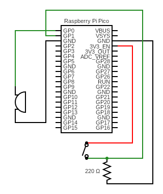
Follow the diagram below to set up a circuit for the buzzer and button.
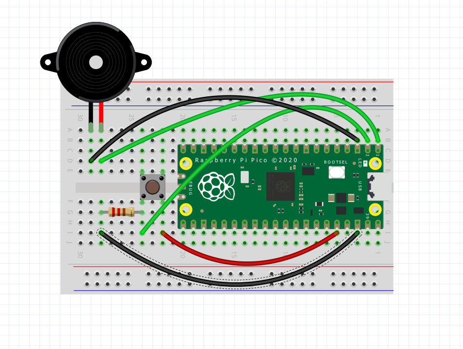
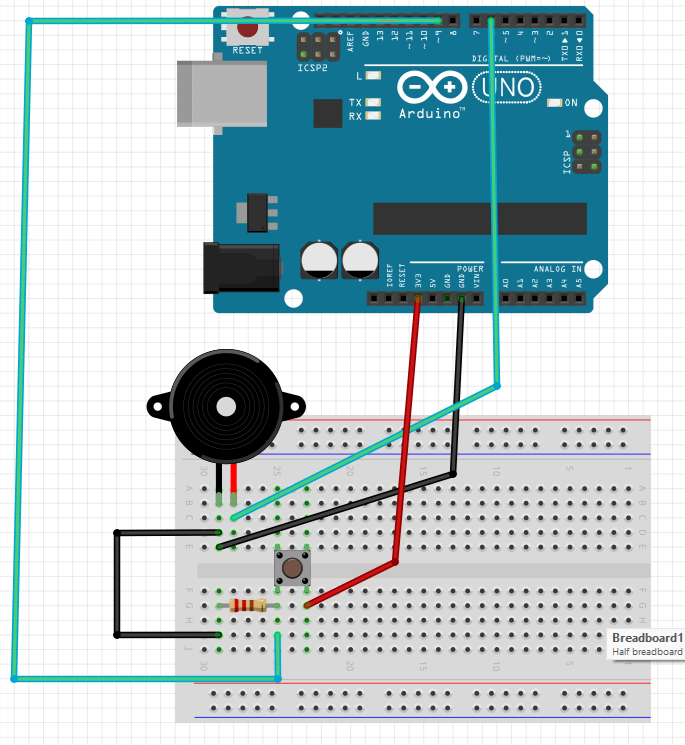
Note: The LED’s bent pin in the diagram represents the positive (longer) pin
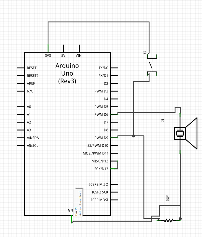
There is nothing new going on here. We have the same arrangement as for the LED with button except the buzzer can handle more current and does not need a resistor.
Duty Cycle vs Frequency#
For buzzers compared to LEDs, we have two parameters to consider that can change sound outputs, frequency and duty cycle.
In terms of the signal:
Duty cycle is the % of each cycle/period in which the signal is high vs low.
Frequency is the number of cycles/periods per second.
In terms of sound, the difference is:
Duty cycle affects the loudness of the buzzer and is measured as a %. Lower values will yield quieter outputs.
Frequency affects the pitch of the buzzer and is measured in Hz. Lower values will yield lower pitched notes while higher values will yield higher pitches.
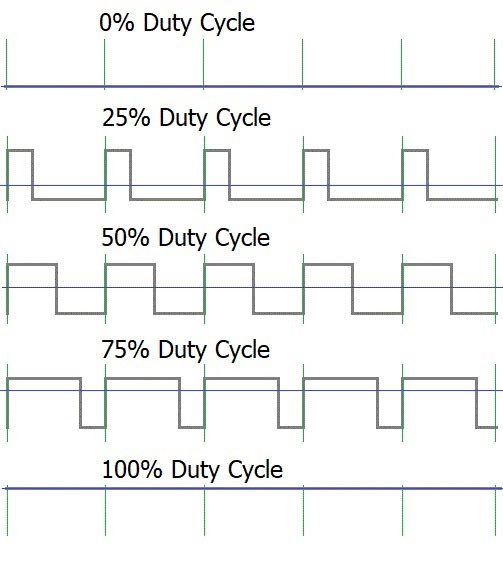
To understand the difference between the two we can again consider the same figure:
These different signals all have different duty cycles but have the same period (shown by the green vertical lines) and thus the same frequency.
In order to change the frequency, we would change the the period of each signal. In the diagram, to increase the frequency we would squeeze the lines closer together while to decrease the frequency we would widen them apart. Doing this would not affect the duty cycle since the % high vs low remains the same.