
Automated LED - Writing the code#
We can now write our first program to blink the LED.
Open your code editor and write up the code you see below. If you have connected your LED to a pin other than GP0 or 13, make sure you change this in the code.
import board
import time
import digitalio

#change below to be correct pin that LED is connected to
led = digitalio.DigitalInOut(board.GP0)
led.direction = digitalio.Direction.OUTPUT

while True:
    led.value = True
    time.sleep(0.5)
    led.value = False
    time.sleep(0.5)
When you are done upload to your microprocesser
Click save and make sure the file named code.py is on the CIRCUITPY drive
Watch out!
If you don’t see any changes, remember to double check you are not in the REPL. If you are, you can exit with CTRL-D.
// This is the blink example that is available through Arduino IDE
https://www.arduino.cc/en/Tutorial/BuiltInExamples/Blink
int led = 13    //set the pin number
// the setup function runs once when you press reset or power the board
void setup() {
  // initialize digital pin LED_BUILTIN as an output.
  pinMode(led, OUTPUT); //set pin 13 (led) to be an output
}

// the loop function runs over and over again forever
void loop() {
  digitalWrite(led, HIGH);  // turn the LED on (HIGH is the voltage level)
  delay(500);                      // wait for 0.5 second
  digitalWrite(led, LOW);   // turn the LED off by making the voltage LOW
  delay(500);                      // wait for 0.5 second
}
When you are done upload to your microprocesser
Click compile and upload, making sure the Arduino is connected
Watch out!
Make sure the code compiles correctly. If not use the compile error to find the problematic bit of code
If both your circuit and your code are correctly set-up, you should now see your LED blinking!
We’ll know go through what each line is doing.
Importing Modules#
import board
import time
import digitalio
Every CircuitPython program you write, will begin with import statements. These statements allow us to use key functions from modules built into the CircuitPython program.
board - This module allows us to refer to specific pins on the Pico
time - This module contains functions that allow us to keep track of time while running programs.
digitalio - This module is used for sending and receiving digital signals.
It is very likely you will need the board and time modules for all CircuitPython programs you write. You will need digitalio for any system with simple digital inputs and/or outputs. There are other modules for other types of input/output, which we will see in later tutorials.
Arduinos do not need to import libraries to have access to board info, timing or controling IO. Often however you will need to include a library
For example, to include the math libary add the following at the top of the Arduino code
#include math
Defining Inputs/Outputs#
led = digitalio.DigitalInOut(board.GP0)
led.direction = digitalio.Direction.OUTPUT
Next we need to create variables to represent all of the inputs and outputs present in our circuit.
Since we only have an LED present, we have used led. The variable name itself isn’t important but you must use the same name throughout your code.
The first line here creates the variable led to control our and assigns it as a digital object using digitalio.DigitalInOut(). To do this we further need to use board.GP0 - which is a further object representing the GP0 pin on our Pico.
We then set the led.direction as an Output using digitalio.Direction.OUTPUT.
Case by case
Python is case sensitive meaning led, Led and LED will not be treated as the same variables.
int led = 13    //set the pin number
// the setup function runs once when you press reset or power the board
void setup() {
  // initialize digital pin LED_BUILTIN as an output.
  pinMode(led, OUTPUT); //set pin 13 (led) to be an output
}
Next we need to create variables to represent all of the inputs and outputs present in our circuit.
Since we only have an LED present, we have used led. The variable name itself isn’t important but you must use the same name throughout your code.
The first line here creates the variable led and sets it to 13, this is the pin. Then the line inside the set up function sets this pin to be an output using the pinMode function
Case by case
Arduino C is case sensitive meaning led, Led and LED will not be treated as the same variables.
Creating a loop#
while True:
    led.value = True
    time.sleep(0.5)
    led.value = False
    time.sleep(0.5)
Having defined the inputs/outputs we are using, we can now write code for specific actions.
While loops
while loops are essential for CircuitPython programs and are very common in Python generally..
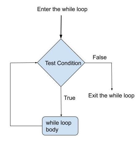
Fig. 9.1 Logical structure of While loops#
Anything indented under the while loop is treated as the body and will be repeated as long as the condition is true.
Here, our condition is simply set to True which means that this loop will run indefinitely. Without while True:, the program would run only once and then stop.
Assigning output values
Once we have created a while loop, we can then give an action to be repeated.
Our first action given is led.value = True, which turns our LED on.
led.value is an object that represents the state of our LED. Since our LED is recognised as a digital output, this can be either True which means the LED is on, or False meaning it is off.
With led.value = True, we are effectively telling the Pico to supply power through pin GP0 and turn the LED on. Note that the default setting for any digital output is False.
Next, the time.sleep() function takes a time in seconds and pauses further actions on the microcontroller for that amount of time. This is known as a blocking function, meaning it stops all other actions from being completed while running. Since our LED has just been switched on, using time.sleep(0.5) leaves the LED on for half a second.
Once this half a second is up, led.value = False switches the LED back to off. This is then followed by another half a second delay as a result of time.sleep(0.5).
Since we are in an infinite loop, after the last line of code the Pico will return to the first line and execute the exact same actions.
See for yourself
Try changing the number in either/both time.sleep() functions and press save to see how the blinking changes.
Explore the options
As with all coding, there are many alternative ways to program the same action.
A more concise option which yields the same output as above is given below
while True:
    led.value = not led.value
    time.sleep(0.5)
// the loop function runs over and over again forever
void loop() {
  digitalWrite(led, HIGH);  // turn the LED on (HIGH is the voltage level)
  delay(500);                      // wait for 0.5 second
  digitalWrite(led, LOW);   // turn the LED off by making the voltage LOW
  delay(500);                      // wait for 0.5 second
}
A loop is automatically created for you by the Arduino code. Anything inside the loop() function will run continuously as long as the Arduino is powered
Assigning output values
As we have a loop we can then give an action to be repeated.
Our first action given is digitalWrite(led, HIGH), which turns our LED on.
digitalWrite() is function that sets the state of our LED. Since our LED is recognised as a digital output, this can be either True which means the LED is on, or False meaning it is off.
With digitalWrite(led, HIGH), we are effectively telling the Pico to supply power through pin 13 and turn the LED on. Note that the default setting for any digital output is False.
Next, the delay() function takes a time in milliseconds and pauses further actions on the microcontroller for that amount of time. This is known as a blocking function, meaning it stops all other actions from being completed while running. Since our LED has just been switched on, using delay(500) leaves the LED on for half a second.
Once this half a second is up, digitalWrite(led, LOW) switches the LED back to off. This is then followed by another half a second delay as a result of delay(500).
Since we are in an infinite loop, after the last line of code the Arduino will return to the first line and execute the exact same actions.
See for yourself
Try changing the number in either/both delay() functions and press save to see how the blinking changes.
Here, != is an operator meaning ‘not equal to’. This means that each time the loop restarts, led.value is set to the opposite of what it currently is and the LED switches from Off to On or vice versa.
Exploring ways to make code more efficient through clever logic can be one of the most rewarding aspects of programming!